#esp32 development board
Explore tagged Tumblr posts
Visit Tumblr Blog
Explore Tumblr blogs with no restrictions, modern design and the best experience.
Last Seen Tumblr Blogs


Fun Fact
Tumblr’s website traffic is steadily declining.
Text
Espressif programmer test success! 💻✨🔧
While developing boards, there are oftentimes we want to program ESP chips without going through the onboard USB port; this adapter will help us (and others) do that! It has a CP2102N USB-serial chip
https://www.digikey.com/short/bm7n3p5z
...with RX/TX signal LEDs and two transistors wired up to the DTR/RTS line for the 'esptool standard' reset procedure technique. The output IO, plus a 3.3V 500mA regulated output, is available on a socket header, so you can plug wires in for quick programming and debugging. You can use this for everything from an ESP8266 up to the ESP32-P4! Here, we are testing it with a HUZZAH ESP8266 breakout board
...one of our first Espressif chipset products.
#espressif#esp8266#esp32#programmingtools#embeddeddevelopment#usbserial#cp2102n#diyhardware#electronicsengineering#hardwarehacks#embeddedprogramming#iotdevices#espchip#circuitdesign#prototypingtools#techinnovation#makersmovement#hardwaredevelopment#esp32p4#debuggingtools#huzzah#esp8266projects#techgadgets#microcontrollers#hardwaredebugging#esp32projects#diyelectronics#opensourcehardware#iotprojects#techtools
20 notes
·
View notes
Text
Looking at this as a way to add some extra buttons and a cursor (trackball, touchpad or joystick) to a normal phone by using the usb otg port for the keys and gpio pins for the cursor and communicating over bluetooth. The idea would be to have an adjustable clip on enclosure that goes on the back of the phone (with some specific design stuff to make it ergonomic)
12 notes
·
View notes
Text
Remembered that I was planning to do a thing to the lua_led driver so I sorted out code uploading, and resolved some memory issues. Now I have to do *shudders* web development.
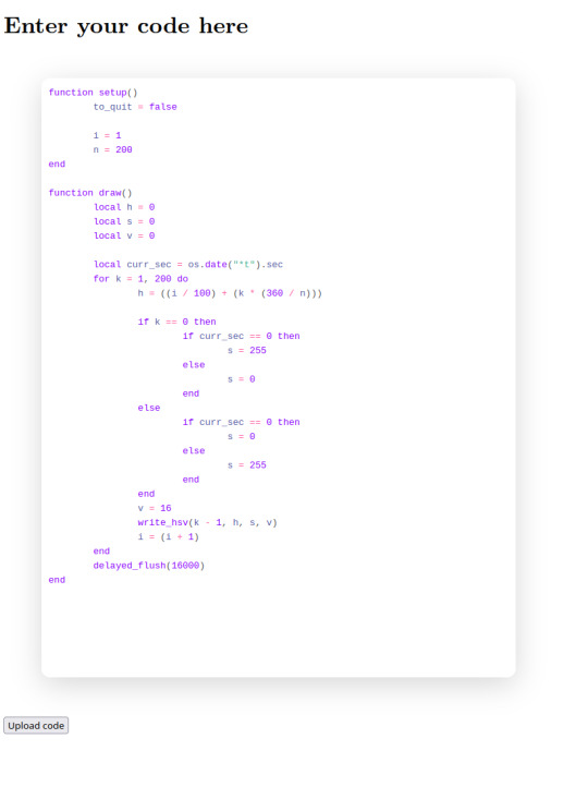
(okay technically there's still a lot of lua and web things to do, it is not robust yet, but you can type in a textbox and hit a button to update the lua code)
I'm trying out Codeflask to jam a nice editor into the onboard flash of this board, I have 4MB, which should be plenty for all the code, a few webpages, and a few hundred kilobytes to store some LED programs. All in the minified versions of this editor with lua highlighting seems to fit in ~40kB which is pretty good.
I don't know how to do UI and at least in theory I want this to all be local to the esp32 so I can't just pull in Patternfly or whatever. Well I've made several dozen webpages without fully understanding CSS and it can't stop me.
7 notes
·
View notes
Text
Super Tiny RP2040/ESP32 Display Development Board
Compact RP2040/ESP32 Powered Display board with Type-C connector, keeps it up to date, easier to use
Support us on Kickstarter today

2 notes
·
View notes
Text
The ESP32 is a development board developed by Espressif systems. It can be programmed using Arduino IDE and ESP-IDF. It has higher processing power than ESP8266 but it is more costly and bigger in physical dimension than ESP8266. It has a built in Bluetooth module and CAN protocol and SRAM. It has 36 GPIO Pins with a CPU clock of 160MHz. It has 12-bit ADC onboard and supports CAN, UART, I2C and I2S. It can be used in prototyping IoT products, Low power Battery operated application, small range networking projects, and with the projects which require many Input Output Pins and Wi-Fi and Bluetooth connectivity.
6 notes
·
View notes
Text
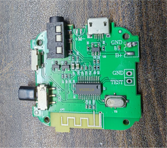
Introducing One Classic application scenarios: A Super Flexible Bluetooth Audio Transceiver Using KT1025A
Ever wanted to build your own Bluetooth audio transmitter/receiver without dealing with bulky modules or complicated stacks? Meet my KT1025A-based Bluetooth audio board – compact, programmable, and packed with features!
What's So Cool About the KT1025A? This chip is a hidden gem for Bluetooth audio: ✔ Supports both TX (transmitter) & RX (receiver) modes – switch roles with firmware! ✔ Low-latency audio streaming – great for gaming, DIY wireless headphones, or car audio. ✔ Built-in DSP effects – bass boost, EQ, and noise suppression without extra ICs. ✔ Single-chip solution – minimal external components, perfect for compact designs.
What I Built My board includes: 🔹 USBfor firmware updates 🔹 3.5mm AUX + I2S breakout – hook up speakers, DACs, or even an ESP32 for Wi-Fi bridging. 🔹 Programmable buttons & LEDs – control playback, pairing, and mode switching. 🔹 External antenna option – better range than most consumer dongles!
Why This Rocks for Makers ✅No obscure proprietary tools – development is done via standard UART/AT commands. ✅Supports MP3, WAV, FLAC, APE format decoding– decent audio quality without licensing headaches. ✅Works out of the box as a Bluetooth receiver (e.g., for old speakers) OR a transmitter (e.g., for TVs without BT).
All schematics, a build guide are up on [Google Drive] (https://drive.google.com/drive/folders/1GNh3ebV4mieyRTAvHUEztJU4eUHxfJLR?usp=drive_link ). If you've ever wanted to turn anything into a Bluetooth audio device, this might be your easiest starting point.
Check out the pics ↓ Would love your feedback!
0 notes
Text
CAN Bus Applications in Medical Devices: Precision Communication in Critical Environments
Discover how CAN Bus technology is revolutionizing medical device communication. Explore real-world examples like infusion pumps, ventilators, and surgical robots, and learn why CAN is ideal for critical healthcare systems.
#can bus#medical devices#can fd#embedded systems#healthcare#medical equipment#surgical robots#ventilator
0 notes
Text
WIRELESS MODULE with BLE and WiFi – ESP32-C3-DevKitM-1 The ESP32-C3-DevKitM-1 from Campus Component is a low-power, cost-effective solution for IoT developers. It combines WiFi and Bluetooth LE connectivity in a compact design. Featuring robust security features and efficient processing capabilities, this board is suitable for smart home devices, health monitors, and industrial IoT systems. It supports Espressif’s ESP-IDF framework.
0 notes
Text

A little Espressif helper for programming
While developing boards, we often want to program ESP chips without going through the onboard USB port; this adapter will help us (and others) do that! It has a CP2102N USB-serial chip
https://www.digikey.com/short/bm7n3p5z
with RX/TX signal LEDs and two transistors wired up to the DTR/RTS line for the 'esptool standard' reset procedure technique. The output IO, plus a 3.3V 500mA regulated output, is available on a socket header, so you can plug wires in for quick programming and debugging. You can use this for everything from an ESP8266 to an ESP32-P4!
#espressif#esp8266#esp32#programmingtools#hardwaredev#cp2102n#usbtoserial#iotdevelopment#debuggingtools#esptool#opensourcehardware#devboards#electronicsproject#makerlife#techinnovation#embeddedengineering#hardwarehack#electronicsdesign#developerlife#codinghardware#prototyping#electronicsengineering#hardwarehacking#chipprogramming#serialadapter#diyelectronics#esp32projects#debugging#iotdevices#electronicsenthusiast
17 notes
·
View notes
Text
This is basically the current main board but with an e-ink display, I agree with the author of the article that this board would probably be very good for messaging even outside. So I'm thinking about input method possibilities for our current board that we could potentially apply to this later on to make it so you could have a handheld PierMesh e2ee (the e2ee might take some futzing around/soldering a coprocessor) messaging device without a phone or anything else.
4 notes
·
View notes
Text
Getting Started with Embedded Systems Programming

Embedded systems programming is the backbone of modern electronics. From smartwatches to washing machines, embedded systems power the intelligent functions of countless everyday devices. This guide will introduce you to the basics of embedded programming, key tools, and how to begin building your own embedded applications.
What is an Embedded System?
An embedded system is a computer integrated into a larger system or device, performing dedicated functions. Unlike general-purpose computers, embedded systems are designed for specific tasks, often with constraints on power, memory, and processing.
Examples of Embedded Systems:
Microcontrollers in home appliances
Sensor-based devices (e.g., temperature sensors, motion detectors)
Medical equipment
Automotive control systems
IoT (Internet of Things) gadgets
Core Components of an Embedded System
Microcontroller or Microprocessor: The brain of the embedded system (e.g., Arduino, STM32, ESP32).
Memory: RAM and ROM to store instructions and data.
Input/Output Interfaces: Connects to sensors, displays, motors, and communication modules.
Software: Custom firmware developed for specific functions, typically in C or C++.
Popular Programming Languages
C: Most widely used due to its efficiency and low-level hardware access.
C++: Used when object-oriented design is required.
Assembly: For highly optimized or time-critical routines.
MicroPython: Python for microcontrollers (e.g., ESP8266, Micro:bit).
Getting Started with Embedded Programming
Select Your Platform:
Beginners: Arduino (easy setup, wide community support)
Advanced: STM32, Raspberry Pi Pico, ESP32
Set Up Your Development Environment:
Install IDEs like Arduino IDE, PlatformIO, STM32CubeIDE
Download necessary drivers and board support packages
Write and Upload Code: Create simple programs like blinking an LED, then expand to sensors, displays, and communication modules.
Example: Blink an LED with Arduino
void setup() { pinMode(13, OUTPUT); // Set pin 13 as output } void loop() { digitalWrite(13, HIGH); // Turn LED on delay(1000); // Wait for 1 second digitalWrite(13, LOW); // Turn LED off delay(1000); // Wait for 1 second }
Tools and Debugging
Serial Monitor: For real-time debugging and logging.
Oscilloscope & Logic Analyzer: For electrical signal inspection.
In-Circuit Debuggers: Like JTAG or ST-Link for low-level debugging.
Best Practices
Write modular and readable code.
Use debouncing for physical inputs like buttons.
Handle memory carefully to avoid overflows.
Optimize power usage in battery-powered devices.
Conclusion
Embedded systems programming is both fun and powerful, offering endless possibilities for innovation in hardware and software. Whether you’re building a home automation project or diving into the world of IoT, understanding the basics of embedded programming gives you the foundation to create smart, responsive devices.
0 notes
Link
[ad_1] In today’s era of the Internet of Things (IoT), smart home automation has evolved from being a luxury to an accessible and essential part of modern living. This project demonstrates a scalable and real-time home automation system built around the powerful IndusBoard Coin, a compact development board based on the ESP32-S2 microcontroller. The system allows users to wirelessly control multiple AC appliances like lights and fans through an interactive web interface hosted directly on the board itself, without requiring any external cloud services or mobile apps. Unlike traditional automation systems that only offer ON/OFF control through relays, this project takes a step ahead by integrating PWM-based fan speed control, enabling smooth real-time adjustment of AC fan speed via a slider on the webpage. The board generates PWM signals from its GPIO pins, which are then sent to an AC Fan Speed Controller module that modulates the fan speed accordingly. At the same time, standard relay modules are used to control the switching of lights and fans. The Coin board’s GPIOs are connected to the relay modules, acting as electronic switches for turning appliances ON or OFF with a simple tap on the web interface.- Advertisement - The system runs on Wi-Fi Access Point (AP) mode by default, allowing users to connect their phones or laptops directly to the IndusBoard’s Wi-Fi (SSID: IndusBoard_AP) and access the control panel through a browser. However, this can easily be modified to Station Mode (STA), where the board connects to your home Wi-Fi network. In this mode, any device on the same network can access and control the system through the board’s local IP address, enabling seamless integration into existing smart homes. One of the major advantages of using the IndusBoard Coin is its high number of available GPIOs (30+ pins), which means this system is not limited to just two lights and a fan. It can be easily scaled to control additional appliances by simply connecting more relays or PWM controllers to unused GPIOs and expanding the user interface accordingly. - Advertisement - For example, additional buttons and sliders can be added to the webpage to control more lights, fans, or even future sensors like motion detectors, temperature sensors, or LDRs. Fig. 1: Home Automation System UI Bill of Material ComponentsQuantityDescriptionIndusBoard Coin1IndusBoard CoinRelay Module (5V)1Channel Relay Module (5V) 250V ACFan Speed Controller Module1Fan Speed Controller Module5V DC Adapter15V DC Circuit Diagram Fig. 2: Circuit Diagram Here, IndusBoard Coin acts as the central brain of the entire smart home automation system. It not only processes control commands but also establishes wireless communication by creating a Wi-Fi Access Point (AP mode) or by connecting to an existing Wi-Fi network using Station (STA) mode. Through this connectivity, the Coin board hosts a real-time interactive webpage that allows users to control connected appliances directly from a browser. Using its multiple GPIO pins, the board sends digital control signals to various actuators such as relays and fan speed controller modules. The relay modules, connected to GPIO pins (for example, GPIO 3 for Light 1 – GPIO 6 for Light 4), serve as the switching interface for AC appliances like bulbs or fans. These relays function as electrically operated switches, toggled by the digital HIGH or LOW outputs from the Coin board. For fans, while a regular relay can only turn the fan ON or OFF, integrating a fan speed controller module, such as an AC dimmer or a PWM-compatible controller, enables variable speed control. This module receives a PWM signal—typically from a pin like GPIO 21—where the duty cycle or firing angle of the signal determines the actual fan speed. This allows for a smooth and precise adjustment of fan speed directly through the web interface, providing a complete and advanced smart automation experience. The relay module acts like an electronic switch that isolates and safely controls the AC side of the circuit. Each relay channel on the module has input control pins connected to one of the GPIO pins of the Coin board (for instance, GPIO 3 is connected to control Light 1, and GPIO 6 to control Light 2). When a digital HIGH signal is sent from the Coin board to the relay input pin, it triggers the internal electromagnetic coil inside the relay, which closes (or opens) a switch on the AC side, allowing current to flow through the connected appliance. To connect an AC bulb or other AC appliance, the Live (L) wire from the mains power supply is first connected to the Common (COM) terminal of the relay. The Normally Open (NO) terminal is then connected to one terminal of the AC bulb or appliance. The other terminal of the appliance is connected directly to the Neutral (N) wire of the mains supply. When the relay is activated by the Coin board, the circuit between COM and NO closes, completing the path and powering ON the appliance. When the relay is deactivated, the circuit breaks, and the appliance turns OFF. This configuration ensures that high-voltage appliances are safely switched using the low-voltage logic level control from the Coin board, keeping the user and the controller board isolated from dangerous AC voltages. Multiple such relays can be connected to multiple GPIO pins on the IndusBoard Coin to control several appliances individually and in real time from the web interface. Additionally, the system can be expanded easily due to the availability of over 30+ GPIO pins on the Coin board, making it highly scalable and adaptable for larger smart home setups. Code Fig. 3: Code for Wirelessly Control Multiple AC Appliances with Web Interface The code begins with the definition of GPIO pins assigned to control various appliances like lights and fans. After that, a simple and interactive HTML webpage user interface (UI) is created within the code using embedded HTML and JavaScript, allowing users to control appliances in real time through any browser. The pinMode() function is used in the setup section to configure each GPIO pin as an output. The Wi-Fi settings are configured to enable Access Point (AP) mode, so the IndusBoard Coin can create its own wireless network for users to connect directly. The code also initializes the web server, defines routes to handle button clicks and fan speed control commands, and continuously checks for incoming client requests in the loop to ensure smooth operation of the automation system. Testing fig 4. Webpage UI for automation Now, power on the device and relay. Then, open the Wi-Fi settings on your phone or laptop and search for IndusBoard_AP. Connect to it using the password set in the code. Next, open a web browser and enter 192.168.4.1 in the address bar. From there, you can control appliances such as light bulbs, fans, and AC units. Use the slider bar to adjust the speed and the text input to set automation. The system will automatically turn off all appliances after the specified time. [ad_2] Source link
0 notes
Text

ESP32 WROVER Kit, Compatible with Arduino IDE The starter kit is based on the development board from esp32 wrover. It integrates with bluetooth and wireless.A powerful dev board for IOT module project development.ESP32-WROVER series is developed by Espressif Systems, below is key features and applications are summarized: I. ESP32 Wrover Specifications - Chip Architecture - Dual-core SoC (ESP32-D0WD or D0WD-V3) with a clock speed of 80–240 MHz (dynamic frequency scaling)13 - 520 KB integrated SRAM, expandable via external SPI RAM/Flash1 - Built-in 4–16 MB SPI Flash and 8 MB SPI PSRAM (depending on model, e.g., WROVER-B/E)37 - Wireless Connectivity - 2.4 GHz Wi-Fi (802.11 b/g/n) with up to 150 Mbps throughput36 - Dual-mode Bluetooth: Classic (BT) and Low Energy (BLE)36 - Peripherals & Interfaces - SPI, I2C, UART, SDIO, Ethernet interfaces3 - Support for capacitive touch, Hall effect sensors, PWM outputs37 II. ESP32 Wrover Kit Development Environment & Tools - Programming Frameworks - Official ESP-IDF framework (FreeRTOS + LwIP stack), C/C++-based16 - Arduino IDE compatibility via ESP32 board manager28 - Optional Python/C hybrid development using Zerynth Studio5 - Hardware Debugging Tips - Use 5V power for camera modules (3.3V may cause image instability)2 - Adjust SPI pin definitions (e.g., SCK=14, MISO=12) based on hardware layout4 III. ESP32 Devkit Typical Applications - IoT Devices - Sensor networks, smart home controllers with ultra-low-power modes (sleep current Read the full article
0 notes
Text
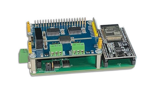
Introducing the ESP32 with Dual Isolated CAN Bus Port
Enhance CAN bus communication reliability with the ESP32 Development Board and Dual Isolated CAN Bus HAT. Discover the benefits of galvanic isolation in automotive and industrial applications.
1 note
·
View note